Installation
Recommendation for use
No other types of installation are permitted than those in subchapters 5.3 and 5.4
External device dimensions IRF34x1
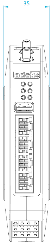
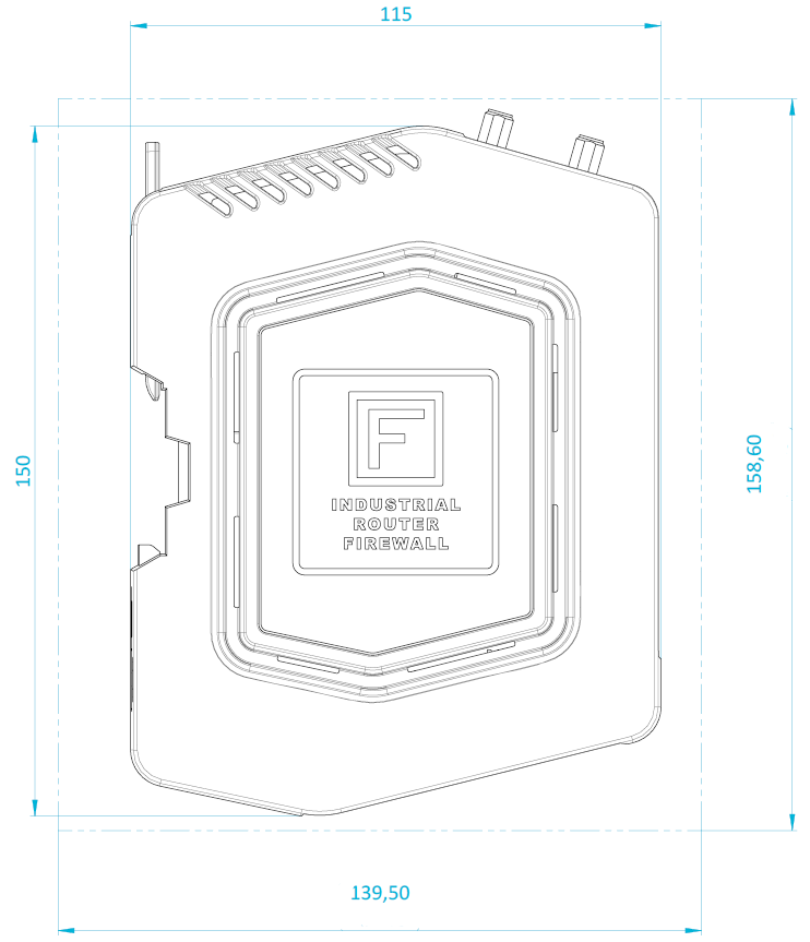
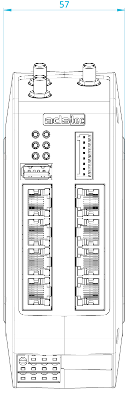
External device dimensions IRF38x1
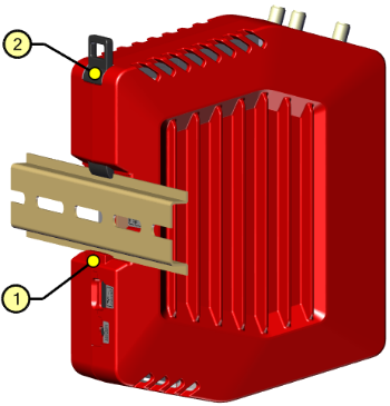
Top-hat rail mounting
1. Position the IRF on the top-hat rail from below at an angle (1).
2. Pull the top-hat rail locking mechanism (2) upwards using a screwdriver, push the device onto the upper side of the top-hat rail and remove the screwdriver.
3. The top-hat rail locking mechanism springs back to its original position.
4. Check that the IRF is seated securely on the top-hat rail.
 |
To release the device from the top-hat rail, proceed in the reverse order.
Recommendation for use
When removing, take care not to damage the top-hat rail adapter of the device.
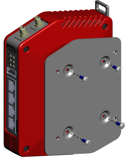
Optional accessory: Attaching the VESA holder
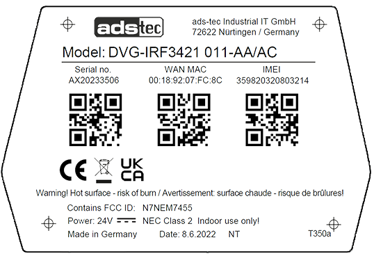
Screw the mounting plate directly onto the device label using the screws provided. The positions of the screw holes are marked with target crosses ( ) on the label.
  |
Optional: Attaching antennas
-
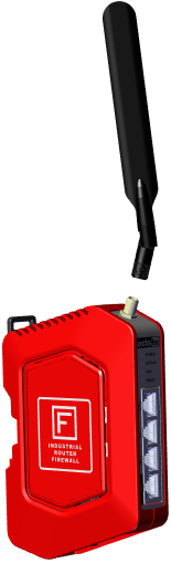
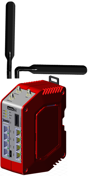
Screw the mobile communications antennas to the antenna connections (WWAN AUX/MAIN) directly or via an SMA extension cable.
-
Screw the SMA cable of the GPS antenna to the GNSS connection.
 |