Output map
Navigation: Configuration > I/Os > Output map
The Output map tab defines the logical assignment between the software functions on the device and the physical output signals on the device connector. Each mapping entry links a named software function (e.g., ALARM, VPNUP) to a hardware output (e.g., a digital output DO or an LED). Use this tab to configure which physical output is activated when a given software function triggers. For an overview of the CUT and alarm behavior configured on the main I/Os page, see the Input map tab for input assignments, or the State tab to monitor the current signal state in real time.
Settings
Output map
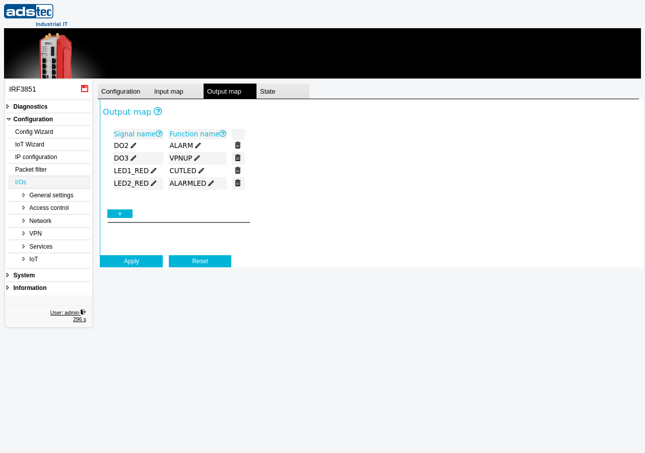
The output map is presented as a table with one row per mapping entry. Use the + button to add a new mapping entry, or the delete icon to remove an existing one.
- Signal name
- The I/O signal name on the physical connector of the device. This identifies which hardware output is being mapped. The value can be edited inline. Typical signal names include DO2, DO3 for the digital outputs, and LED1_RED, LED2_RED for the front-panel LED indicators.
- Function name
- The name of the software function that activates the corresponding output signal. This determines which internal device event drives the physical output. The value can be edited inline. Typical function names include ALARM (alarm condition), VPNUP (VPN tunnel established), CUTLED (CUT status indication), and ALARMLED (alarm LED indication).