Packet filter
Navigation: Configuration > Packet filter
The packet filter page controls which network traffic is permitted or denied as it passes through the device. The Layer 3 packet filter operates on IP packets traveling between interfaces that have their own IP addresses — this includes all interfaces in IP router and IP router (extended) mode, but also applies in transparent bridge mode for interfaces that remain routed (e.g. WWAN, Docker, Big-LinX VPN). The filter is the primary tool for enforcing network segmentation and access control. It operates on a system of rule sets, each containing up to 10 individual rules. Rule sets are evaluated from top to bottom: when a packet matches a rule, the configured action is applied and processing stops. If no rule in any matching rule set applies, the packet is dropped by default. This deny-all fallback behavior ensures that only explicitly permitted traffic can traverse the device. The packet filter complements the Forwarding and 1:1 NAT pages for more advanced traffic steering. For filtering on bridged (switched) interfaces, use the Layer 2 tab.
Prerequisites
- At least two interfaces with independent IP addresses must be present for Layer 3 filtering to apply. In IP router and IP router (extended) mode, all interfaces are routed and can be filtered. In transparent bridge mode, the LAN interfaces are bridged (use Layer 2 filtering for those), but WWAN, Docker, and Big-LinX VPN interfaces still have their own IP addresses and can be filtered with Layer 3 rules. Configure the operational mode on the IP configuration page.
- Plan your security policy before creating rules. Determine which traffic flows between interfaces must be allowed and which must be blocked.
- If Network groups or Hardware groups are used as source or destination criteria, define them on their respective configuration pages before referencing them in packet filter rules.
Settings
Packet filter Layer 3
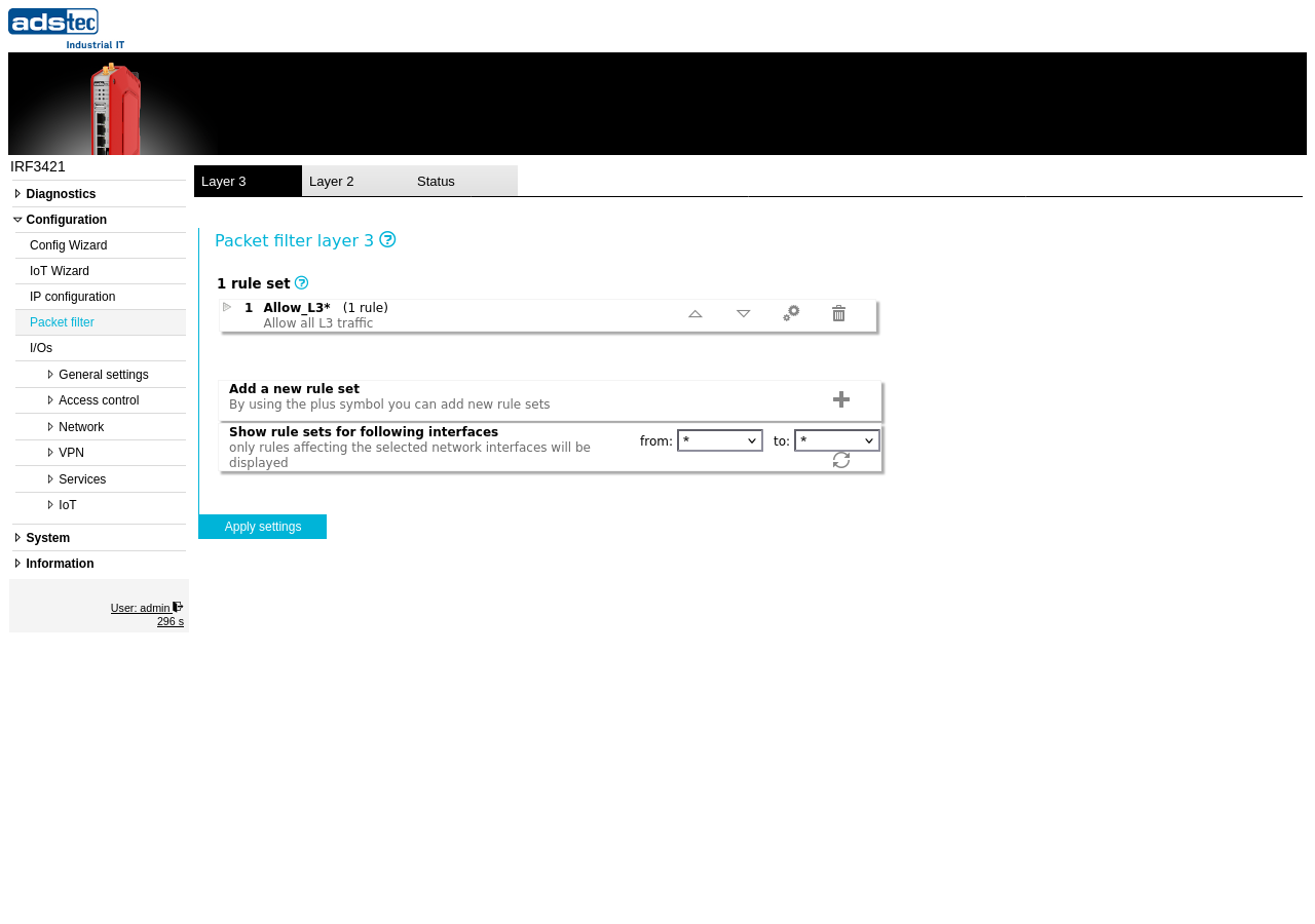
The Layer 3 packet filter filters all packets passing through the device on routed network interfaces.
The filter is organized into rule sets. Each rule set is defined by a name, a source interface, and a destination interface. Within a rule set, individual rules specify detailed match criteria such as protocol, IP addresses, and ports, along with the action to take when a match occurs.
- Rule sets
-
The main area of the page displays all configured rule sets in their evaluation order. Each rule set shows its name, the number of rules it contains, and a brief description. Rule sets can be reordered using the up and down arrow buttons, edited using the gear icon, or deleted using the trash icon. The order of rule sets is significant: packets are matched against rule sets from top to bottom based on their source and destination interface.
Packets pass through the packet filter from top to bottom. If a rule set's source and destination interface match the packet, the rules within that set are evaluated in order until a match is found. Processing stops at the first matching rule and the corresponding action is applied. If no rule within a matching rule set applies, the packet is passed to the next rule set. If no rule set matches at all, or no rule within any matching set matches, the packet is dropped.
- Add a new rule set
- Click the + button to create a new rule set. A new rule set requires a name, a source interface, and a destination interface. Once created, individual rules can be added to define match criteria and actions.
- Show rule sets for following interfaces
- Filters the displayed rule sets by source and destination interface. Use the from and to dropdowns to select specific interfaces, or leave both set to * to display all rule sets. This filter affects only the display and does not change the active configuration.
ATTENTION
The default policy is to drop all traffic that does not match any rule. When creating a new configuration, ensure that all required traffic flows are explicitly permitted before applying the settings. Applying an incomplete rule set may cause immediate loss of network connectivity, including remote management access to the device.
Security
Follow the principle of least privilege: allow only the specific protocols, ports, and address ranges required for your application and deny everything else. Avoid broad "allow all" rule sets in production environments. Review rule sets regularly to remove obsolete entries and verify that no unintended access paths exist. In accordance with IEC 62443, restrict traffic between network zones to the minimum necessary for plant operation to reduce the attack surface.
Rule set wizard
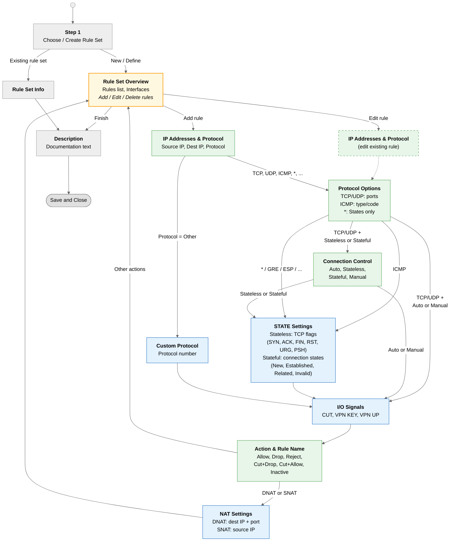
Clicking the + button or the edit icon on an existing rule set opens a multi-step wizard for defining rule sets and rules. The wizard guides through all configuration options; the steps shown depend on the protocol and connection control mode selected. The following diagram shows all possible paths through the Layer 3 rule set wizard.
Choose or create a rule set

Select an existing predefined rule set or create a new one. Predefined rule sets (Allow_L3, Block_L3, ICMP_L3, Log_L3) provide common starting configurations. Predefined rule sets can be modified after copying them with the Copy button. A rule set may contain up to 10 filter rules. Currently active rule sets are grayed out and cannot be selected again.
- Name of the new rule set
- When Define a new rule set is selected, enter a unique name for the new rule set.
Rule set overview

Displays all rules in the current rule set. From here, rules can be added, edited, reordered, or deleted. The interface selectors at the top define which source and destination interfaces this rule set applies to.
- Overview of rule set
- The name of the rule set. For user-defined rule sets, this field is editable.
- Inbound interface
- The network interface on which incoming packets are matched. Select a specific interface or * for all interfaces.
- Outbound interface
- The network interface on which outgoing packets are matched. Select a specific interface or * for all interfaces.
IP addresses and protocol

Define the source and destination IP addresses and select the IP protocol for this rule.
- Source IP address/mask
- The source IP address and subnet mask to match. Leave empty or use * to match any source address. Enter an IP address with a subnet mask to match a network range (e.g. 192.168.1.0 / 255.255.255.0).
- Use network groups
- When enabled, select a predefined network group instead of entering an IP address manually. Network groups are defined on the Network groups page.
- Destination IP address/mask
- The destination IP address and subnet mask to match. Same format as source address.
- IP protocol
- The IP protocol to match. Available options: * (any), TCP, UDP, ICMP, IPv6, GRE, ESP, AH, IPIP, ENCAP, Other. The selected protocol determines which additional options appear in the next wizard step.
Protocol options — TCP/UDP ports

This step appears when TCP or UDP is selected as the IP protocol.
- Source port
- The source port number to match. Use * for all ports. Enter a single port number (e.g. 80) or a range using a colon (e.g. 1024:65535 for all ports above 1023).
- Destination port
- The destination port number to match. Same format as source port. Common values: 80 (HTTP), 443 (HTTPS), 22 (SSH), 502 (Modbus TCP).
Protocol options — ICMP type

This step appears when ICMP is selected as the IP protocol. Select the ICMP message type to match. The most common types are echo-request (ping) and echo-reply (ping response).
Connection control

This step appears for TCP and UDP rules. It determines how the firewall handles the return traffic (response packets) for connections matching this rule.
- Connection control
-
Select the connection tracking mode:
- Auto — Automatically generates the necessary rule for session traffic in the opposite direction. This is the recommended setting for most use cases.
- Stateless (TCP only) — Allows checking individual TCP header flags (SYN, ACK, FIN, RST, URG, PSH) in the next step. A separate rule for the opposite traffic direction must be created manually.
- Stateful — The stateful filter memorizes the connection state. Connection state parameters (New, Established, Related, Invalid) can be configured in the next step. A separate stateful rule for the opposite direction must be created manually.
- Manual — Complete manual control without any connection state tracking.
STATE settings — Stateless (TCP flags)

This step appears when Stateless connection control is selected for a TCP rule. It allows matching on individual TCP header flags to determine the connection state.
For each TCP flag (SYN, ACK, FIN, RST, URG, PSH), two options are available:
- to check
- When enabled, this flag is included in the matching criteria.
- activate (bit is set)
- When enabled together with "to check", the flag must be set in the packet. When only "to check" is enabled but "activate" is not, the flag must be cleared.
STATE settings — Stateful (connection states)

This step appears when Stateful connection control is selected. Select which connection states this rule should match:
- State new — Matches packets that establish a new connection.
- State established — Matches packets belonging to an already established connection.
- State related — Matches packets related to an existing connection (e.g. FTP data channel).
- State invalid — Matches packets that do not belong to any known connection.
I/O signals

Allow or reject packets based on the state of the device's input/output signals. This makes filter rules dependent on physical signal conditions — for example, allowing traffic only when a hardware key switch is in a specific position.
For each signal (CUT, VPN KEY, VPN UP), two options are available:
- Check signal
- When enabled, the signal state is included in the rule matching criteria.
- Signal high
- When enabled together with "Check signal", the signal must be at high voltage level. When only "Check signal" is enabled but "Signal high" is not, the signal must be off (no voltage).
Action and rule name

Define what happens when a packet matches all criteria of this rule.
- Action
-
Select the action to perform:
- Allow — The packet is forwarded.
- Drop — The packet is silently discarded.
- Reject — The packet is discarded and an ICMP error message is sent to the sender. The reject reason can be configured (e.g. net-unreachable, host-unreachable, port-unreachable).
- Cut + Drop — The network link is cut at hardware level and the packet is discarded.
- Cut + Allow — The network link is cut at hardware level and the packet is forwarded.
- Inactive — The rule is stored but not applied to traffic.

- Reject reason
- Only available when Reject is selected. Determines the ICMP error message sent back to the sender: net-unreachable, host-unreachable, port-unreachable, proto-unreachable, net-prohibited, or host-prohibited.
- Log
- When enabled, a log entry is created for each packet matching this rule.
- Audit
- When enabled, packets matching this rule are logged to the audit log. The audit logging is limited to one packet per minute and logs only IPv4 source, destination, and protocol.
- Alarm
- When enabled, the alarm output is triggered when a packet matches this rule.
- Max. packets/s
- Limits the maximum number of packets per second processed by this rule. Leave empty for no rate limit.
- Rule name
- A unique name to identify this rule within the rule set.
Rule set description
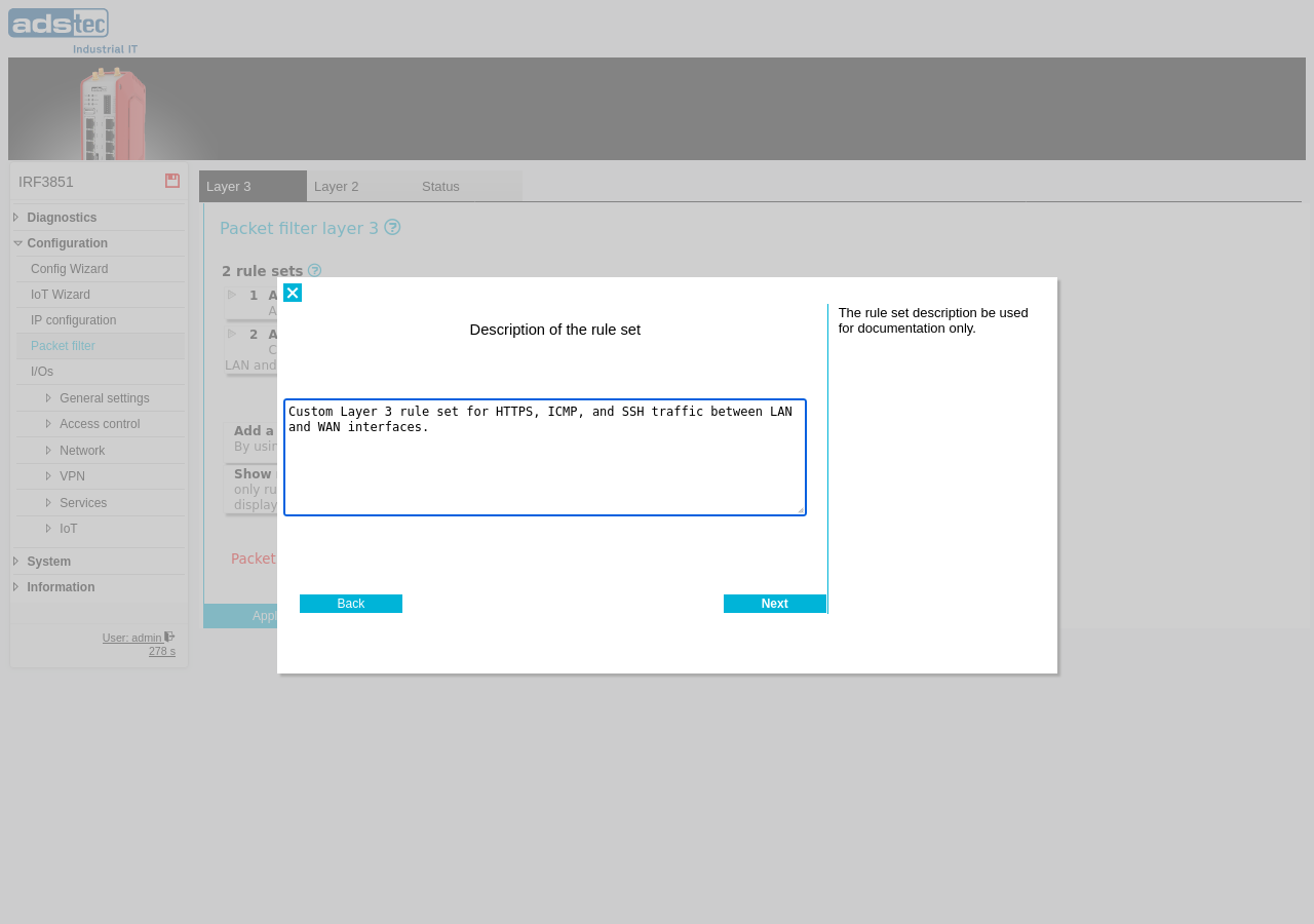
Enter an optional description for the rule set. This text is used for documentation purposes only and does not affect packet filtering.
Rule set activity
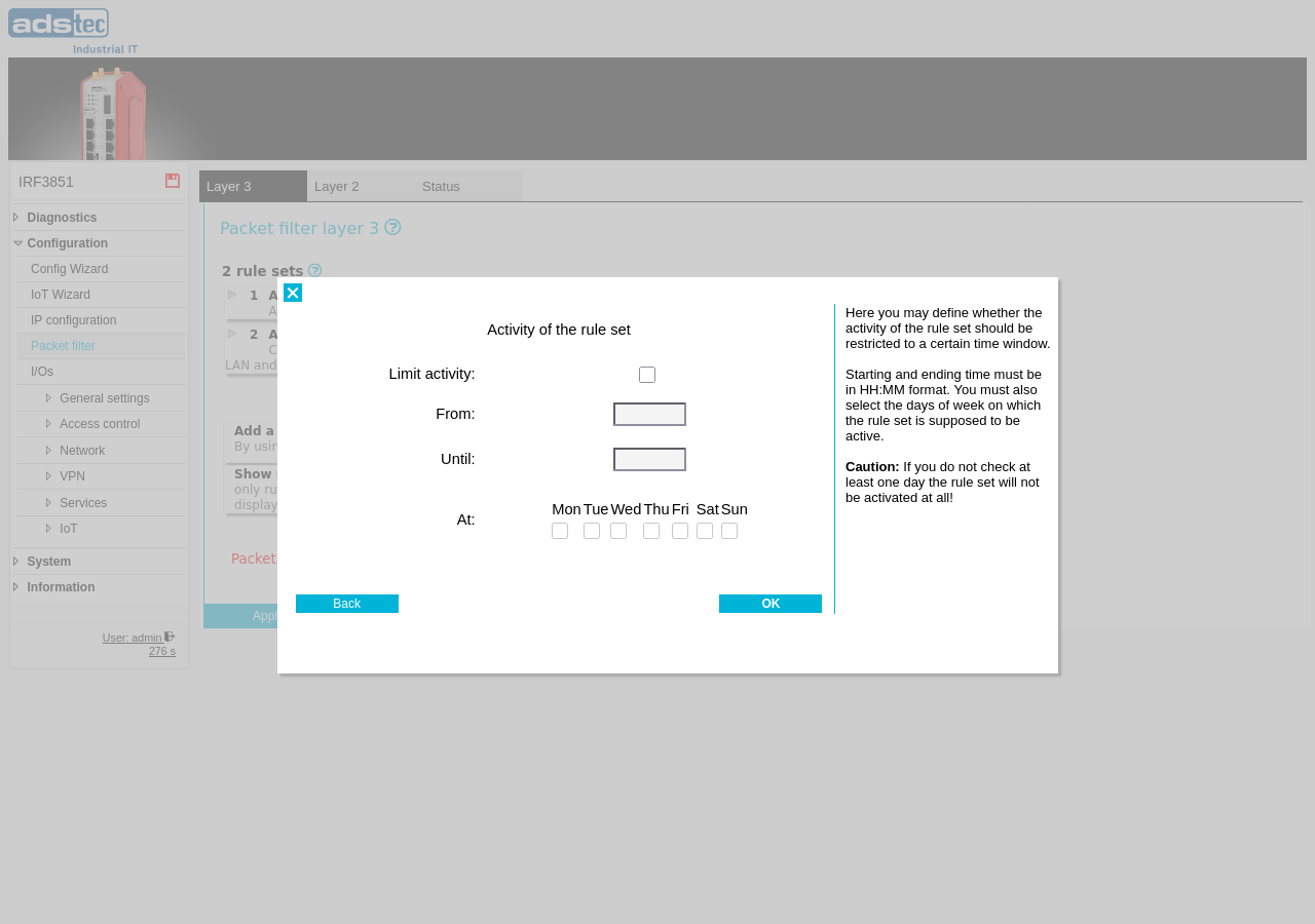
Configure time-based activation for the rule set. When activity limiting is enabled, the rule set is only active during the specified time window and on the selected days of the week. Outside the configured schedule, the rule set is inactive and its rules do not apply to traffic.
- Limit activity
- When enabled, restricts the rule set to the configured time window and days.
- From / Until
- The start and end time for the activity window (24-hour format, e.g. 08:00 – 17:00).
- Mon – Sun
- Select the days of the week on which the rule set should be active.