CAN Bus
Navigation: Configuration > IoT > Sources > CAN Bus
The CAN Bus page configures the CAN (Controller Area Network) interface of the IRF3851, used to acquire industrial data from a connected CAN bus. It sets the CAN bit rate, optional CAN FD (Flexible Data-rate) operation with its own data-phase bit rate, listen-only mode, bus-error reporting, and automatic bus-off recovery. The live interface status — bit timing, error counters, and controller mode — is shown on the State tab. Changes take effect after clicking Apply, but must be saved persistently via the Save page to survive a reboot.
Note
The CAN interface is available only on models equipped with CAN hardware (e.g. the IRF3851). On the IRF3851 the CAN bus shares a 12-pin connector with digital I/Os 3…5.
Use from Docker
The CAN bus can be accessed from Docker containers running on the device. Enable CAN access for containers on the Docker page.
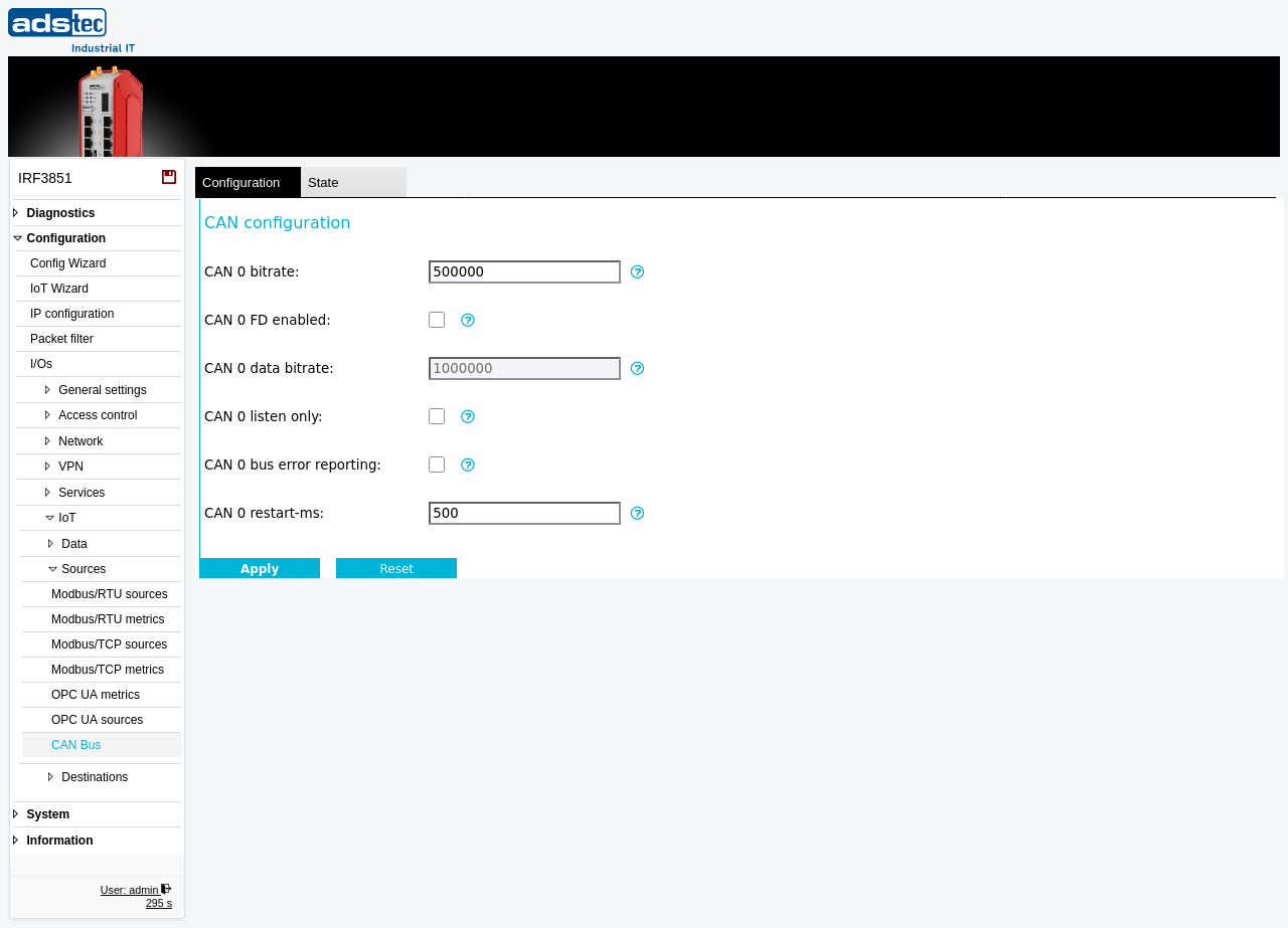
Settings
- CAN 0 bitrate
- The CAN 0 bit rate in bits/s (the arbitration-phase bit rate). It must match the bit rate of the connected CAN bus.
- CAN 0 FD enabled
- Enables CAN FD (Flexible Data-rate) for CAN 0. When enabled, the data phase uses the separate data bit rate below.
- CAN 0 data bitrate
- The CAN 0 data bit rate in bits/s for the data phase of CAN FD frames. Only used when CAN FD is enabled.
- CAN 0 listen only
- When enabled, CAN 0 only listens and does not send any frames or acknowledgments (passive monitoring of the bus).
- CAN 0 bus error reporting
- Enables bus-error reporting for CAN 0.
- CAN 0 restart-ms
- The automatic-restart time in milliseconds after a bus-off condition (0 disables automatic restart).
CAN connector and wiring
On the IRF3851 the CAN bus shares a 12-pin (2×6) connector with digital I/Os 3…5. The CAN signals are on pins 9–12; for the complete connector pin assignment see Electrical interfaces.
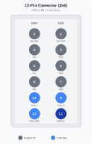
| Pin | Signal | Description |
|---|---|---|
| 9 | CAN_H | CAN high line |
| 10 | CAN_L | CAN low line |
| 11 | CAN_SHIELD | Cable shield |
| 12 | CAN_GND | CAN reference ground |
Recommended wiring
- Use a twisted pair for CAN_H (pin 9) and CAN_L (pin 10).
- Connect CAN_GND (pin 12) to the CAN reference ground of the bus system.
- Route the cable shield continuously and connect it to CAN_SHIELD (pin 11).
- Use a linear bus topology; avoid a star topology and keep branch lines (stubs) as short as possible.
Termination
- Fit 120 Ω termination resistors only at the two physical ends of the CAN bus.
- An IRF3851 used as a mid-node must not add extra termination.
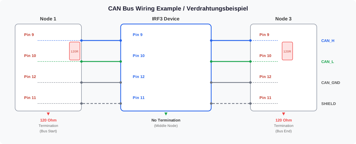
Commissioning checklist (physical connection)
- CAN_H (pin 9) and CAN_L (pin 10) are not swapped.
- CAN_GND (pin 12) is connected.
- The shield is connected to pin 11.
- Exactly two 120 Ω termination resistors are present, one at each bus end.