Modbus/RTU sources
Navigation: Configuration > IoT > Sources > Modbus/RTU sources
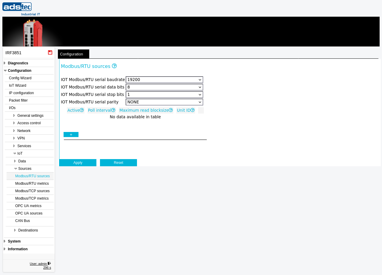
This page configures the Modbus/RTU slave devices from which the device polls data via the RS-485 serial interface. Each entry in the source table represents one Modbus slave on the serial bus, identified by its unique unit ID. The page also defines the serial communication parameters (baud rate, data bits, stop bits, parity) that apply to all devices on the bus. Once sources are configured here, the specific registers to read from each source are defined on the Modbus/RTU metrics page. The IoT Wizard can assist with initial setup of the complete IoT data acquisition chain. Changes take effect after clicking Apply settings, but must be saved persistently via the Save page to survive a reboot.
Prerequisites
- The device must be equipped with an RS-485 serial interface. Verify that the RS-485 port is physically wired to the Modbus slave devices.
- All Modbus slave devices on the bus must use the same serial communication parameters (baud rate, data bits, stop bits, parity). Consult the documentation of each connected device for its serial settings.
- Each slave device must be assigned a unique Modbus unit ID (bus address) before connecting it to the bus.
Settings
Serial parameters
The serial parameters apply globally to the RS-485 bus. All Modbus/RTU slave devices connected to the same bus must be configured to use identical serial settings.
- IOT Modbus/RTU serial baudrate
- The baud rate for the serial RS-485 communication. Common values are 9600, 19200, 38400, 57600, and 115200. The default is 19200. This value must match the baud rate configured on all connected Modbus slave devices.
- IOT Modbus/RTU serial data bits
- The number of data bits per serial frame. Typical values are 7 or 8. The default is 8. This must match the data bit setting of all connected slave devices.
- IOT Modbus/RTU serial stop bits
- The number of stop bits per serial frame. Typical values are 1 or 2. The default is 1. This must match the stop bit setting of all connected slave devices.
- IOT Modbus/RTU serial parity
- The parity checking mode for the serial communication. Available options are NONE, EVEN, and ODD. The default is NONE. This must match the parity setting of all connected slave devices.
Source table
The source table lists the Modbus/RTU slave devices to be polled. Use the + button to add a new source entry.
- Active
- Enables or disables polling for this source entry. Inactive entries remain in the configuration but are not polled.
- Poll interval
- The interval in seconds at which the configured registers are read from this source. A shorter interval provides more frequent data updates but increases bus traffic. Choose a value appropriate for the rate of change of the monitored process data.
- Maximum read blocksize
- The maximum number of contiguous registers that can be read in a single Modbus request from this source. This value depends on the capabilities of the slave device. If the slave does not support large block reads, reduce this value to avoid communication errors.
- Unit ID
- The Modbus unit ID (bus address) of the slave device. Each slave on the RS-485 bus must have a unique unit ID. Valid values typically range from 1 to 247.
ATTENTION
The unit ID must be unique for each slave device on the bus. Duplicate unit IDs cause communication conflicts and unpredictable behavior. The serial parameters (baud rate, data bits, stop bits, parity) must be identical across all devices sharing the same RS-485 bus. A mismatch in any serial parameter prevents reliable communication.
Security
The RS-485 serial interface provides no built-in authentication or encryption. Any device physically connected to the bus can participate in Modbus communication. Restrict physical access to the RS-485 wiring and the device's serial port. Only enable Modbus/RTU source polling if IoT data acquisition from serial devices is actively required. Disable unused source entries to reduce unnecessary bus traffic and limit the operational attack surface.